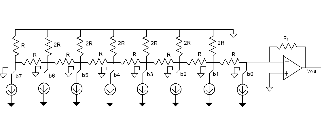
Simple Analog to Digital Converter under Repository Circuit Diagram In electronics, an analog-to-digital converter (ADC, A/D, or A-to-D) is a system that converts an analog signal, such as a sound picked up by a microphone or
I'm trying to hook up a sip-puff air pressure sensor which outputs 0v to 5v depending if the pressure is -ve (sipping) or +ve (puffing).I want to use it to drive a Bluetooth keyboard controller to help a disabled person use an iPad.When pins on the Bluetooth controller are driven low, they send a key press - the idea being when you sip it sends key 'a' and when you puff it sends 'b'. For example a 4-bit ADC will have a resolution of one part in 15, (2 4 - 1) whereas an 8-bit ADC will have a resolution of one part in 255, (2 8 - 1). Thus an analogue to digital converter takes an unknown continuous analogue signal and converts it into an "n"- bit binary number of 2 n bits.. But first let us remind ourselves of the differences between an analogue (or analog) signal

How to make Analog to Digital Converter (ADC) Circuit Diagram
Learn how to make a successive approximation (SAR) Analog to Digital Converter (ADC) that's relatively fast…well, as fast as you want to make it. Using some This is a simple type of ADC you can create at home with fairly common parts. I know I skipped over some details like some component values and specific conc
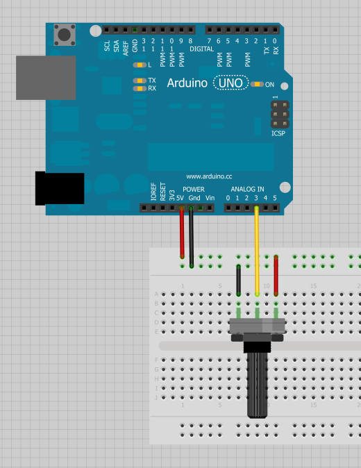
In electronic hardware design, an Analog-to-Digital Converter (ADC) is essential for converting continuous analog signals into discrete digital numbers, enabling digital systems to process analog input signals. Simple all-in-one app. Recall and act upon what matters. Designed with privacy in mind. OMI NECKLACE: DEV KIT Order your Omi Dev Digital Signal: A digital signal is a signal that represents data as a sequence of discrete values; at any given time it can only take on one of a finite number of values. Analog Signal: An analog signal is any continuous signal for which the time varying feature of the signal is a representation of some other time-varying quantity i.e., analogous to another time varying signal. Analog pins in Arduino: Arduino has 6 analog channels for reading analog signals of 0 to 5 Volts. Each channel has a separate analog pin. ATmega328P microcontroller has an inbuilt Analog Digital converter with 10-bit resolution. Analog pins in Arduino only can read the analog input. It cannot reproduce the analog voltage.